As explained in the post about atmospheric effects, the scattering of light by molecules and aerosols in the atmosphere brings about several effects : scattering adds some haze on the images (the atmospheric reflectance), lessens the signal from the surface (the atmospheric transmission), and blurs the images (the adjacency effects). This post is about the adjacency effects, the other aspects have already been quickly explained in the above post. The figure on the right shows the types of paths that light can follow before getting to the satellite.  Path 1 corresponds to the atmospheric reflectance, path 2 is path that interacts with the target, it is the one which is useful to determine the surface reflectance, paths 3 and 4 contribute to the total reflectance but interact with the surface away from the target. These paths are thus the cause of adjacency effects and they blur the images. If not corrected, adjacency effects may cause large errors. Let’s take the case of a fully
  developed irrigated field surrounded by bare soil. For such a case, the second figure on the right shows the relative percentage of errors for reflectances and NDVI as a function of aerosol optical thickness, if adjacency effect is not corrected. An approximate correction can be applied, but it thus requires to know the aerosol optical thickness. In our MACCS processor, here is how it works :
- We first correct the images under the assumption that the Landscape is uniform. We obtain a surface reflectance under uniform absorption which is noted \( \rho_{s,unif} \).
- We compute the neighbourhood reflectance (\( \rho_{s,adj} \)) using a convolution filter with a 2km radius, that computes the average neighborhood reflectance weighted by the distance to the target. To be fully rigorous, this filter should depend on the optical thickness and on the viewing and sun angle (The less aerosols, the larger radius), but as we did not work on an accurate model, we used a constant radius.
- We correct for the contribution of paths 3 and 4 using :
\( \rho_{s}=\frac{\rho_{s,unif}.T^{\uparrow}.\frac{1-\rho_{s,unif}.s}{1-\rho_{s,adj}.s}-\rho_{s,adj}. T_{dif}^{\uparrow}}{T_{dir}^{\uparrow}} \)
- where \( T^{\uparrow}=T_{dif}^{\uparrow}+T_{dir}^{\uparrow}\) is the total upward transmission, sum of diffuse and direct upward transmissions, and s is the atmosphere spheric albedo. These quantities depend on the wavelength, on the aerosol model and on the AOT. They are computed using Look up Tables based on radiative transfer calculations.
As this processing uses convolution with a large radius, it takes quite a large part of the atmospheric processing time.
Result Exemples
The images below show 3 stages of the atmospheric processing, for 2 Formosat-2 images obtained over Montreal (Canada) with a 2 days interval. The first image was acquired on a hazy day (aerosol optical thickness (AOT) of 0.47 according to MACCS estimate); and the second one on a clear day (AOT=0.1).
- The first line corresponds to the Top Of Atmosphere images, without atmospheric correction. The left image is obviously blurred compared to the right image.
- The second line corresponds to the atmospheric correction under uniform landscape assumption (as in step 1). The left image is still obviously blurred compared to the right image.
- the third line show the same images after adjacency effect correction. In that case, the left image is not blurred any more, it is even maybe a little over corrected as it seems somewhat sharper that the right image.
 |
 |
|---|
TOA Images (On the left, the hazy image)
 |
 |
|---|
Surface reflectance under uniform landscape assumption (on the left, the hazy image)
 |
 |
|---|
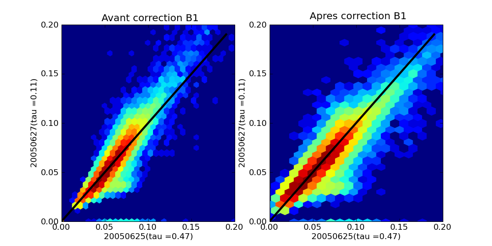
Surface reflectance after adjacency effect correction (on the left, the hazy image) The pixel wise comparison of reflectances is also a way to show the enhancement due to the adjacency effect correction. The plot below compares the images of both dates corrected under the uniform landscape assumption (on the left), and after adjacency effect correction (on the right). You may observe that the dots are closer the the black diagonal on the right. On the hazy image (May 27th), the high reflectances are a little too low, while the low reflectances are a little too high, which is the symptom of a loss of contrast.

