![]() Caution, this post contains formulas.
Caution, this post contains formulas.
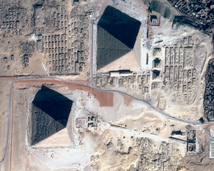
Terrain effects are one of the disrupting elements of surface reflectance retrieval. This can be easily checked with the image below.
The topographic (or terrain) effects on the observed reflectances are due to several phenomena, illustrated below :
- the closer the surface is perpendicular to sun direction, the more energy it receives per surface unit (we talk about irradiance). If the surface is parallel to sun direction, it does not receive direct sunlight. We can model it this way :
- For an horizontal surface : \( E_h= E_0.T_{dir}^\downarrow.cos(\theta_s) \)

Definition of sun zenith angle and sun incidence angle
- For a sloped surface \( E_i=E_0.T_{dir}^\downarrow.cos(\theta_i) \)
- \( E_0 \) is the Top of Atmosphere irradiance, and \( T_{dir}^\downarrow \) is the downward direct transmission, i.e. the proportion of the light that reaches directly the surface without being scattered by the atmosphere.
- Assuming that all the irradiance is direct, the measured reflectance if the surface was horizontal is calculated from the following formula:\( \rho_h=\rho_i \frac{cos(\theta_s)}{cos(\theta_i)}\). However, the above assumption is not true and this formula tends to over correct terrain effects
- For an horizontal surface : \( E_h= E_0.T_{dir}^\downarrow.cos(\theta_s) \)
- The surfaces also receive a diffuse sun irradiance scattered by the atmosphere. If the surface is not horizontal, a part of the sky is obscured by the slope reducing the diffuse irradiance. Moreover, the diffuse irradiance depends on the amount of aerosols (and clouds) in the atmosphere. In addition, the surrounding terrain can also hide a part of the sky, but we do not take this effect into account here in our modelling. We use the following approximation, which is equivalent to assuming that the slope is alone in a horizontal region.
- If surface is horizontal, the visible sky fraction is 1, if it is vertical, this fraction is 1/2
- \( \displaystyle F_{sky}= \frac{1+cos(slope)}{2} \)
- Finally, the slope can receive light from surrounding surfaces, which become directly visible. In our simplified model, we always assume the entire environment of our slope is flat and,for instance, we do not take the effect of the opposite side in a valley into account :
- If surface is horizontal, the visible ground fraction is 0, if it is vertical, it is 1/2.
- \( \displaystyle F_{fround}= \frac{1-cos(slope)}{2} \)
Finally, we use the following formula to compute the reflectance that would be observed if the surface was horizontal \( \rho_{h}\), as a function of the slope (inclined) reflectance \( \rho_{i}\) :
\( \rho_{h}=\displaystyle \rho_{i}.\frac{T^{\downarrow}}{T_{dir}^{\downarrow}.\frac{cos(\theta_i)}{cos(\theta_s)} + T_{dif}^{\downarrow} F_{sky} + T^{\downarrow} F_{ground} \rho_{env}} \)
où \( T^{\downarrow}\) is the downward transmission, sum of direct and diffuse irradiances : \( T^{\downarrow}= T_{dir}^{\downarrow}+ T_{dif}^{\downarrow}\), and [/latex]\rho_{env}[/latex] is the average reflectance of the neighbourhood.
Finally, we can also account for bidirectional reflectance effects, but this correction is tricky since directional effects depend on the surface cover type. See for instance : Dymond, J.R.; Shepherd, J.D. 1999: Correction of the topographic effect in remote sensing. IEEE Trans. Geosci. Remote Sens. 37(5): 2618-2620.
It is very difficult to validate the correction of directional effects : , we could compare the correction results for satellite overpasses at different times in the day. But all the satellite optical imagers have nearly the same overpass time. A qualitative way of estimating the accuracy is to check that similar land covers on opposite slopes in a valley ( a meadow, a forest) have a similar reflectance after correction. The most suitable points are North-South valleys. Here are some examples of terrain effects correction results.

Finally, an essential part of the method’s accuracy is the availability of a highly accurate digital elevation model (DEM), up to now, only the SRTM DEM is available globally, and it only has a 90 meter resolution. Its accuracy is somewhat inadequate and sometimes leaves artefacts if the slope changes are poorly located.
The key to an accurate topographic correction, as demonstrated in your formulas, is to get the exact value of downward direct transmission. But how can we get this value in our correction? Would you please show me some details?
We estimate the downward transmission from radiative transfer calculations, taking into account the aerosol properties determined in earlier phases of the atmospheric correction. I would not assert that is is an « exact » value, but it still enhances the results compared to no correction…
Thanks for all your excellent explanations, a pleasure to read! Have you also looked into using the bottom-of-atmosphere radiance as for example shown in Shepherd & Dymond (2003)? Although I’m not sure if you could get ‘boa’ radiance from SMAC.Because when looking at this equation, in the extreme case, when almost all radiation becomes diffuse. The ‘correction factor’ for the reflectence becomes 1. So the shadow-side of mountains is probably not corrected as much as you would like.
Hi Rutger, thanks for the nice comment.\nThis work was really inspired by the work of Dymond and Shepherd, but I converted and adapted their formula in reflectance instead of radiance. I use the BOA reflectance in the formula.\n\nAnswering your question about the extreme case required some thinking… :\n- am I right if I say that if all the light is diffuse, we do not need to make a correction (except for the sky factor and the surrounding reflectance), and therefore, the fact that correction tends to one is correct ?\n\nBest regards,\nOlivier
Hey Olivier, thanks for your response. It depends perhaps on how you go to TOA reflectance. If you use the quantification factor (toa = dn / 10000) you scale based on extraterrestrial radiation for a flat surface, which is why slopes facing the sun are bright and slopes facing away are dark. Atmospheric correction doesn’t really alter this effect.For the direct term, the cos(i)/cos(sza) takes the incidence angle into account, but this doesn’t help for slopes facing away from the sun, since the direct part becomes really small (in the extreme case). I think you would still want a correction for those conditions. Also note that clear-sky diffuse radiation still has a large terrain (slope/aspect) dependency in it, see for example figure 1 in Shepherd & Dymond (2003). I think assuming its all homogeneous is only valid (more or less) for overcast/cloudy conditions.I was playing around with the equation using this notebook:http://nbviewer.jupyter.org/gist/RutgerK/5c2e86b799790aedc10d57e9645f8958For the area i used there was a shift between the DEM (SRTM CGIAR) and the Sentinel image, which adds some ‘glow’ around mountains crests.