![]() Beware, this document contains equations Radiometric quantities are numerous and may seem rather complex at first sight. Here is a little guide of the various quantities you might stumble upon when using optical remote sensing data. It might be a little boring, it is full-up with integral formulas, but well, to really understand what images mean, it might be useful. Come on, let’s go, and cheers !
Beware, this document contains equations Radiometric quantities are numerous and may seem rather complex at first sight. Here is a little guide of the various quantities you might stumble upon when using optical remote sensing data. It might be a little boring, it is full-up with integral formulas, but well, to really understand what images mean, it might be useful. Come on, let’s go, and cheers !
Radiometry
The detectors of optical instruments are sensitive to the light energy they receive during an observation period. On a camera, the exposure time corresponds to the interval between opening and closing the shutter. On a digital observation instrument put on a satellite, there usually no shutter, and the term « integration time » is used more often: its duration is often fixed by the electronics of the instrument.The energy received is related to the properties of the observed scene, but also depends on many other parameters related to the instrument itself, which is not practical when, for example, comparing measurements taken by various Instruments. We shall define successively in the next paragraphs physical quantities which gradually allow us to free ourselves from these parameters depending on the instrument in order to obtain a characteristic of the surface observed only. This will require the definition of a whole series of physical quantities: the description of this series of magnitudes may be felt to be boring by students (and even by their professors …), but still it is necessary to understand what is observed.
Energy, spectral energy, spectral sensitivity, Equivalent energy
A detector is sensitive to an energy ε, expressed in joules (j), received during the integration time t i. This energy is provided by photons of various wavelengths. Depending on the scene observed, the spectral energy ε (λ) received in each wavelength varies. The spectral energy is expressed in joules per unit of wavelength (often in j / μm). The instrument spectral sensitivity S (λ) depends also on the wavelength. S (λ) is a unit-less quantity.

The energy an instrument receives during integration time, with a sensivity S(λ) between [λ1, λ2] can be computed as in the following formula :
$$\epsilon=\intop_{\lambda_{1}}^{\lambda_{2}}S(\lambda)\epsilon(\lambda)\, d\lambda$$
For a given instrument, the wider the spectral band [λ1, λ2], the greater the collected energy. To avoid manipulating integrals in the formulas, it is useful to define the equivalent spectral energy as the mean of the spectral energy in the band [λ1, λ2], weighted by the spectral sensitivity. $$\epsilon_{eq\,[\lambda_{1},\lambda_{2}]}=\frac{\intop_{\lambda_{1}}^{\lambda_{2}}S(\lambda)\epsilon(\lambda)\, d\lambda}{\intop_{\lambda_{1}}^{\lambda_{2}}S(\lambda)\, d\lambda}$$The advantage of the equivalent spectral energy is that it no longer depends on the bandwidth if the spectral energy does not vary in the band.
Flux
For a given wavelength, the spectral energy is the integral of the light power that reaches the detector during the integration time. The light power is called Spectral flux and is expressed in watts per unit length (often in W / μm)
$$\phi(\lambda)=\frac{d\epsilon(\lambda)}{dt}$$
As for energy, let’s define the equivalent spectral flux, using the following formula :
$$\phi_{eq\,[\lambda_{1},\lambda_{2}]}=\frac{\intop_{\lambda_{1}}^{\lambda_{2}}S(\lambda)\phi(\lambda)\, d\lambda}{\intop_{\lambda_{1}}^{\lambda_{2}}S(\lambda)\, d\lambda}$$
Developing this equation shows that the equivalent fluxes follow the same equation as the spectral flux :
$$\phi_{eq\,[\lambda_{1},\lambda_{2}]}=\frac{d\epsilon_{eq\,[\lambda_{1},\lambda_{2}]}}{dt}\label{eq:flux-energie-equivalente}$$
The flux which reaches the instrument, is still far from representing only the optical properties of the scene we are trying to measure. It depends, for example, on the detector surface. To get rid of this parameter, it is necessary to introduce a new quantity:the irradiance.
The irradiance
The spectral irradiance is the spectral flux which reaches the detectrr per surface unit ds , it is therefore defined by :
$$E(\lambda)=\frac{d\phi(\lambda)}{ds}$$
Similarly, the equivalent irradiance can be defined by :
$$E_{eq\,[\lambda_{1},\lambda_{2}]}=\frac{\intop_{\lambda_{1}}^{\lambda_{2}}S(\lambda)E(\lambda)\, d\lambda}{\intop_{\lambda_{1}}^{\lambda_{2}}S(\lambda)\, d\lambda}=\frac{d\phi_{eq\,[\lambda_{1},\lambda_{2}]}}{ds}$$
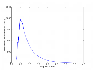
Irradiance makes it possible, to characterize the light power which reaches a surface perpendicular to the light source per unit area. For example, the solar illumination received on land varies with the earth-sun distance, which varies during the year. The solar illumination integrated in the day j for a surface perpendicular to the sun is worth :$$E(j)=E_{0}\frac{d^{2}(j)}{d_{0}^{^{2}}}$$,with E0 = 1367 w / m2 and $$\frac{d^{2}(j)}{d_{0}^{2}}=(1-0.01673*cos(2\pi/365.3*(j-j0-2)))$$, and j0 is the 1st of January 1950. The spectral solar irradiance shows large variations with wavelength.
Irradiance is a useful quantity, but which still depends on the field of view of the detector. The narrower the field of view, the lower the irradiance. It also depends on the orientation of the detector with respect to the direction from which the light comes. For example, if the detector is oriented parallel to the direction of the photons, it will not receive light. Conversely, when the detector is perpendicular to the light direction, it receives a maximum irradance. To obtain a unit independent of the characteristics of the instrument, we will therefore have to define a new quantity (yes, one more …).
The Radiance
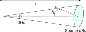
 Definition of solid angle $$d\Omega_{s}=\frac{dS_{s}cos\theta_{s}}{r^{2}}$$. Solid angles are expressed in steradians (sr)The radiance is expressed in w / m2 / sr using the following equation :
$$L(\lambda)=\frac{d^{2}\phi(\lambda)}{ds\, d\Omega\, cos\,\Theta_{s}}$$
The quantity d2G = ds. dΩ . cos Θ s is often used by opticians est and is named throughput. The spectral flux received on a detector whose surface is S and whose field of vue has a solid angle Ω can be written as :
$$\phi(\lambda)=\intop_{S}\intop_{\Omega}L(\lambda)cos\,\Theta_{s}ds\, d\Omega\,=\iint_{G}L(\lambda)d^{2}G$$
As for the quantities above, the equivalent spectral radiance is defined as :
$$L_{eq\,[\lambda_{1},\lambda_{2}]}=\frac{\intop_{\lambda_{1}}^{\lambda_{2}}S(\lambda)E(\lambda)\, d\lambda}{\intop_{\lambda_{1}}^{\lambda_{2}}S(\lambda)\, d\lambda}=\frac{d^{2}\phi_{eq\,[\lambda_{1},\lambda_{2}]}}{ds.d\Omega.cos\,\Theta_{s}}=\frac{d^{2}\phi_{eq\,[\lambda_{1},\lambda_{2}]}}{d^{2}G}$$
When throughput is small, which is usually the case in remote sensing, we get :
$$L_{eq\,[\lambda_{1},\lambda_{2}]}=\frac{\phi_{eq\,[\lambda_{1},\lambda_{2}]}}{G}\label{eq:flux-luminance-=0000E9tendue}$$
The radiance is a unit widely used in remote sensing, since it combines several advantages:
- The energy measured by a detector is proportional to the equivalent luminance. Indeed, for an instrument of geometric extent G, of spectral sensitivity S (λ) in the band [λ1, λ2], which performs measurements during the integration time ti, the measurement X obtained by the detector is proportional to the equivalent radiance :
$$X=\intop_{\lambda_{1}}^{\lambda_{2}}S(\lambda)\epsilon(\lambda)\, d\lambda=\left(\intop_{\lambda_{1}}^{\lambda_{2}}S(\lambda)\, d\lambda\right).\epsilon_{eq\,[\lambda_{1},\lambda_{2}]}.$$ (1)
Using the above equation, we get :
$$X=\left(\intop_{\lambda_{1}}^{\lambda_{2}}S(\lambda)\, d\lambda\right).\phi_{eq\,[\lambda_{1},\lambda_{2}]}.t_{i}=\left(\intop_{\lambda_{1}}^{\lambda_{2}}S(\lambda)\, d\lambda\right).L_{eq\,[\lambda_{1},\lambda_{2}]}.G.t_{i}=S{}_{[\lambda_{1},\lambda_{2}]}.L_{eq\,[\lambda_{1},\lambda_{2}]}.G.t_{i}$$
with $$S_{_{[\lambda_{1},\lambda_{2}]}}=\intop_{\lambda_{1}}^{\lambda_{2}}S(\lambda)\, d\lambda$$,sensitivity of detector within interval [λ1, λ2].
FInally, the equation may be rewritten as :
$$X=A.L_{eq\,[\lambda_{1},\lambda_{2}]} $$.
where A is a constant for a given instrument, that we name absolute calibration coefficient.
- the radiance is independent of the instrument caracteristics.
In equation (1), all the variables are instrument characteristics, except the equivalent spectral luminance, which is independent of the characteristics of the instrument. The measurements obtained are therefore proportional to the radiance of the observed pixel, to a factor (S.G.t) which depends only on the instrument. The designers of the instrument will therefore seek to ensure that S.G.t is:
- as high as possible, to increase sentitivity and signal to noise ratio
- as uniform as possible from one pixel to the other, to avoid large variations within image
Reflectance
For wavelengths under 3 μm, the radiance of land and water surfaces come mainly from the reflection by the earth of the sun irradiance (except for some very intense light sources: projectors directed towards the satellite, lava flows (In the infra red medium) …). The radiance depends on the sun irradiance variable, which depends on the distance between the earth and the sun (variable with the season), and is not therefore a property of the surface, the introduction of a new unit is necessary: it is the reflectance (It Is the last greatness to be defined here, we are at the end of the ordeal).The spectral reflectance is defined by :
$$\rho(\lambda)=\frac{\pi.L(\lambda)}{Es(\lambda,t).cos(\theta_{s})}\label{eq:def reflectance spectrale}$$
And similarly, the equivalent reflectance is defined as :
$$\rho{}_{eq\,[\lambda_{1},\lambda_{2}]}=\frac{\pi.L{}_{eq\,[\lambda_{1},\lambda_{2}]}}{Es{}_{eq\,[\lambda_{1},\lambda_{2}]}(t).cos(\theta_{s})}$$
The above formulation may come as a surprise at first, as one would have expected a much simpler formula, the reflectance being equal to the luminance divided by the illumination. The formula for defining reflectance comes from geometric considerations. The flux received on a surface depends on its orientation with respect to the light source. If the surface is perpendicular to the light rays, the flux is maximum, whereas if it is parallel, it becomes zero. This explains the presence of cos (θs) factor. The normalization factor π ensures that the reflectance is equal to 1 if the surface reflects the entire incident illumination towards the sky. To be convinced, it is sufficient to calculate the integral of the luminance reflected in all directions by a surface whose reflectance is equal to 1 (not forgetting that to integrate on the sphere, it is necessary to use the factor$$sin \theta_{s} d\theta_{s} d\phi$$ and not only $$ d\theta_{s} d\phi$$.
$$\intop_{\theta=0}^{\frac{\pi}{2}}\intop_{\phi=0}^{2\pi}Lsin\theta_{s}d\theta_{s}d\varphi=\intop_{\theta=0}^{\frac{\pi}{2}}\intop_{\phi=0}^{2\pi}\frac{Es.cos\theta_{s}}{\pi}sin\theta_{s}d\theta_{s}d\varphi=\frac{E_{s}}{\pi}\intop_{\theta=0}^{\frac{\pi}{2}}\intop_{\phi=0}^{2\pi}\cdot cos\theta_{s}.sin\theta_{s}.d\theta_{s}d\varphi=E_{s}$$
since :$$\intop_{\theta=0}^{\frac{\pi}{2}}\intop_{\phi=0}^{2\pi} cos\theta_{s}sin\theta_{s}d\theta_{s}d\varphi$$
$$=2\pi.\intop_{\theta=0}^{\frac{\pi}{2}}sin\theta_{s}d(sin\theta_{s})=2\pi\frac{sin^{2}\frac{\pi}{2}}{2}=\pi$$
Reflectance is a property of the surface and does not depend on the instrument observing it or on the irradiance received. This reflectance, however, depends on the angle at which the surface is illuminated and observed and also, of course, on the wavelength. We sometimes use the spectral albedo which is the mean of the reflectance in all directions, or of the albedo, which is the average of the spectral albedo over the whole spectrum :
$$a(\lambda)=\frac{1}{\pi}\intop_{\theta=0}^{\pi}\intop_{\phi=0}^{2\pi}\rho(\lambda).d\theta_{s}d\varphi$$
This time we are at the end of our troubles, and we have demonstrated that the measurements of our satellites are proportional to a property of the surface, the reflectance. It is in reflectance that the data Sentinel-2, or LANDSAT are expressed, although we had to discuss with the supporters of radiance. In fact, reflectance has many advantages :
- Reflectance is an intrinsic property of surface, which only depends on illumination and observation angles (cf directional effects)
- Its values are usually between zero and one, even if values grater than 1 might be observed. These values are easy to remember, contrary to radiance values, which vary from one band to another depending on the sun irradiance
- it is easy to compare reflectances measured in different spectral bands
- It is possible to compare directly reflectances at different times of the year or of the day, without having to account for variations or earth-sun distance or of solar zenith angle


